FAQs
How do I wire and program the control panel NACs for Class A wiring?
Class A fire alarm circuits are designed for high-reliability and fault-tolerance because they use a redundant wiring loop -- signals travel through two separate circuits to ensure continued operation even if one loop is damaged. This involves a primary signal path to all devices and a return path back to the fire alarm control panel, creating a loop.
The Gemini GEMC Commercial Series control panel must include all four NAC circuits; some GEMC-96 and GEMC-32 panels only provide two NAC circuits (NAC A and NAC D) and cannot be configured for Class A wiring.
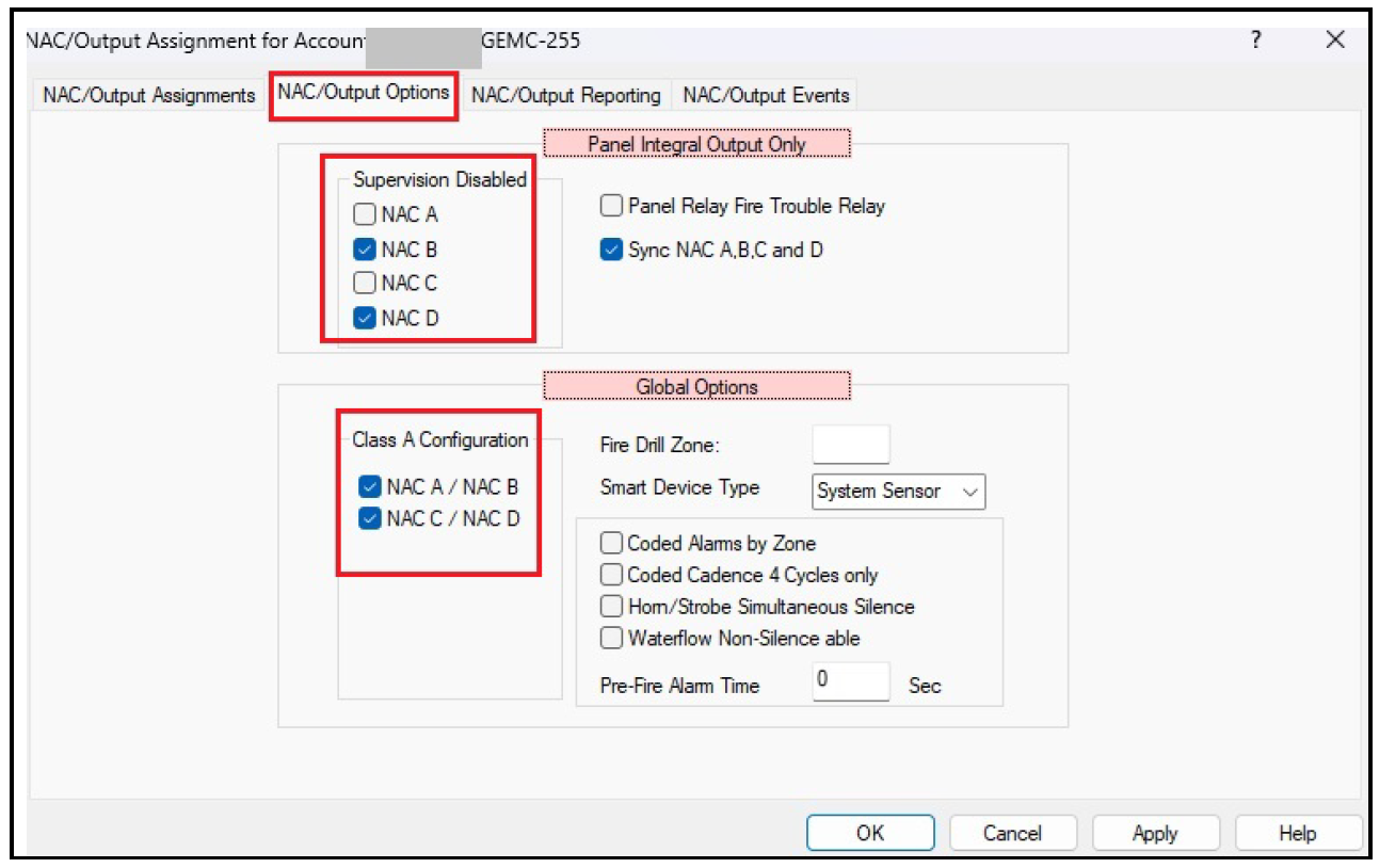
Referring to the image below, the basic programming steps using PCD-Windows Quickloader software are
- Select the NAC/Output Assignments icon
- Select the NAC/Output Options tab.
- In Supervision Disabled, check NAC B and NAC D.
- In Class A Configuration, check NAC A/NAC B and NAC C/NAC D.
- Program your zones to trigger the appropriate NAC circuits (either NAC A, NAC C, or both NAC A and NAC C).
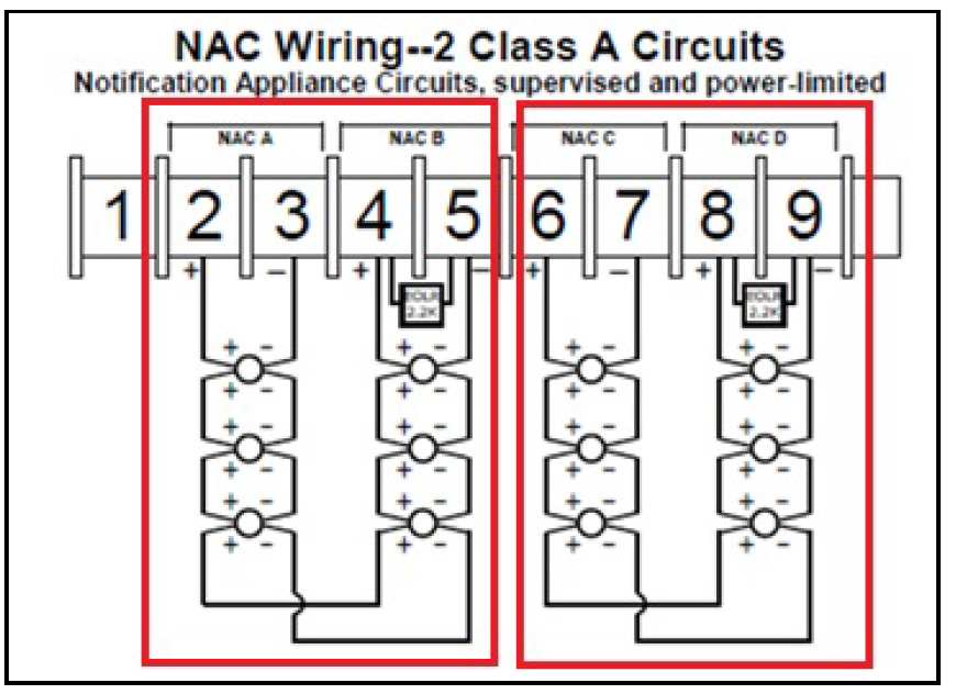
As shown in the image below, the physical wiring of the control panel NAC circuits for the first loop starts as NAC A and returns on NAC B. The second loop starts at NAC C and returns on NAC D.