FAQs
What are the connections and programming steps when using the StarLink Connect and Fire Communicators with the Gemini C-Series (GEMC) control panels?
For the GEMC Fire Side of the GEMC Control Panel:
- Select a StarLink Fire rated communicator model with the Service Plan appropriate for your installation.
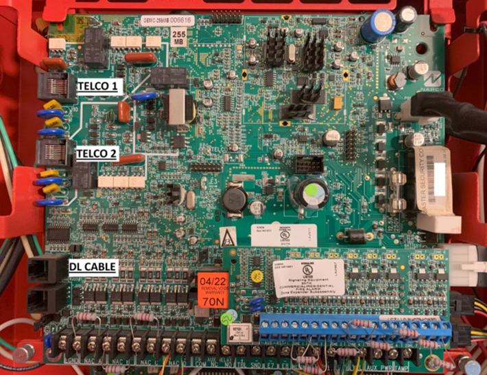
- Connect the download port from the StarLink communicator to the GEMC panel download port (located below the Telco connectors).
- Connect the GEMC Telco port(s) to the StarLink Tip/Ring connections as directed in the instruction manuals.
- Power to the StarLink communicator from non-resettable control panel power. Program your central station information into the StarLink communicator and test the connection.
For the GEMC Burg Side of the GEMC Control Panel:
- Select a StarLink Connect communicator model with either the Basic or Advanced Connect Plan appropriate for your installation.
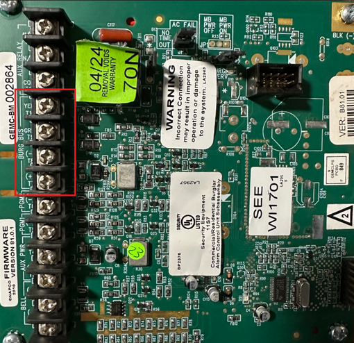
- Connect power to the StarLink communicator from the GEMC-BM Burglary Module keypad/Data Bus and connect the GEMC–BM BURG BUS data connections to TB19 (green) and TB20 (yellow) on the StarLink Connect communicator. Important: Be aware of your total current draw for the Burg side of GEMC control panel; an external power supply may be required depending on the control panel load.
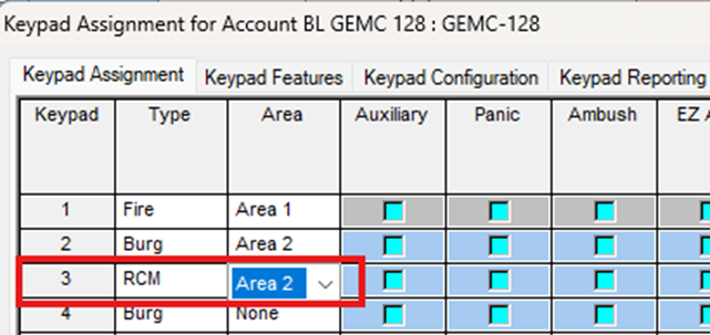
- Control panel programming: Set the StarLink communicator as the next available Keypad number and select RCM as the Type. Be sure to select the correct Burg Area
- StarLink communicator programming: Go to https://napconoc2.com, log in and open your Radio ID. Select the StarLink Connect tab and select Panel Configuration.
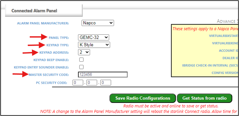
- Under the Connected Alarm Panel heading (example shown below), set:
-
- PANEL TYPE
- Set KEYPAD TYPE to K Style
- Select KEYPAD ADDRESS number to match the panel programming
- Enter your MASTER SECURITY CODE
Select Save Radio Configurations.